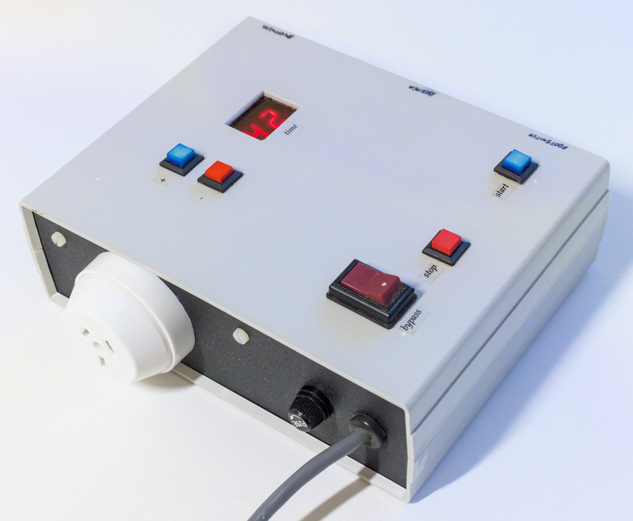
If you have an enlarger in your darkroom you'll need an enlarger timer. Both new and secondhand ones seem to be reasonably easy to obtain, but a new enlarger timer is quite expensive for the functionality required. If you're handy with a soldering iron you can probably build this basic one for less.
Make your own digital enlarger timer
This design is definitely very retro for a piece of electronic equipment. All the timing circuitry is made from cheap and readily available 4000-series CMOS logic chips. If I was designing it today I would base it around a microcontroller instead — something like a Raspberry Pi Pico or Arduino. That would undoubtedly allow more functionality and require less soldering, but the parts would probably cost about the same. The design presented here requires no programming.
Features 🔗
- 1-second to 99-second exposure duration. In practice I found that I very rarely needed any more than 99s, and you can always break up extremely long burns and dodges into multiple stages. The foot-switch makes that easier.
- Beeps every second during countdown.
- Optional foot-switch to start the timer. Handy for complicated burns and dodges when you need to use both hands.
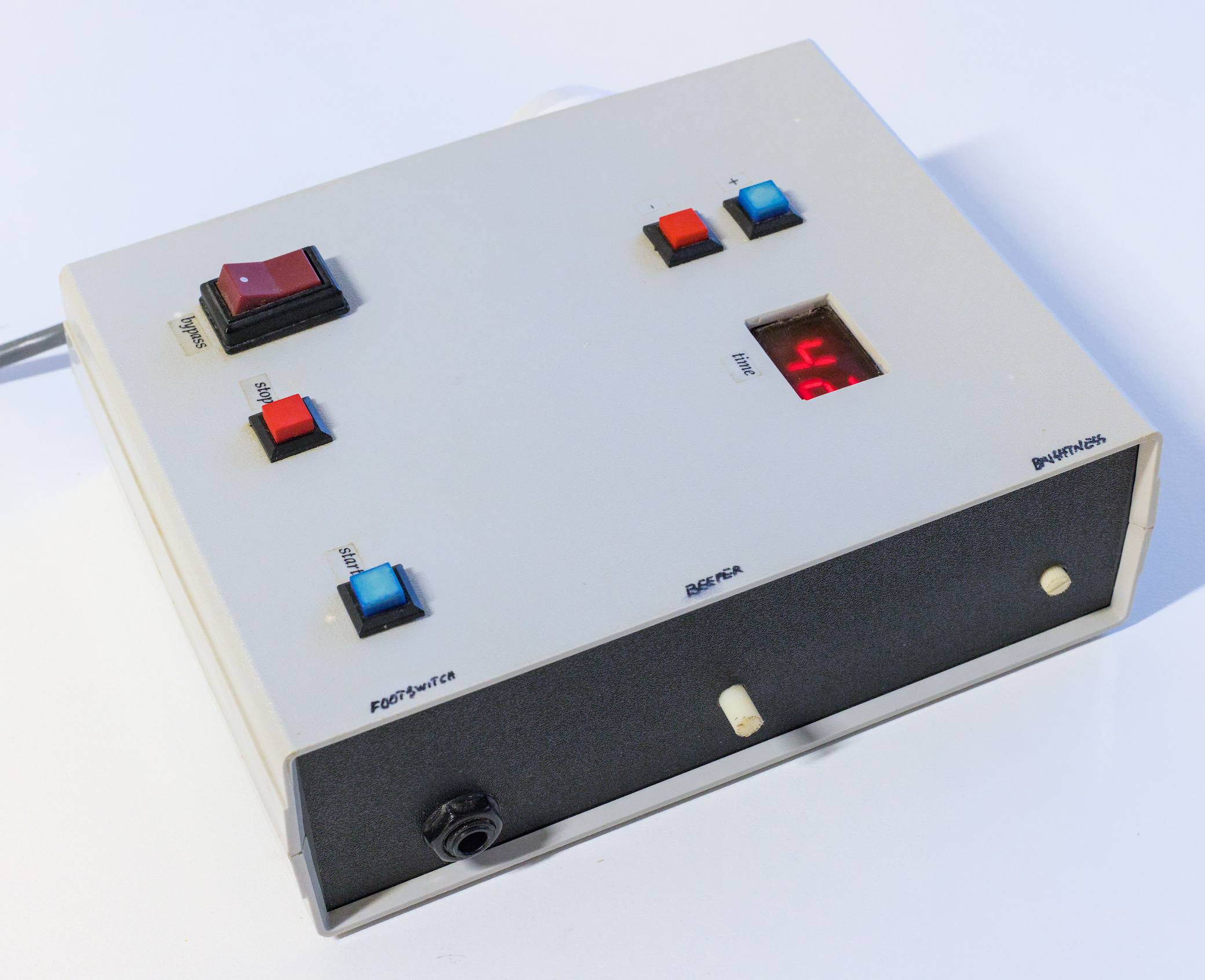
- Adjustable display brightness and beeper volume
- Bypass switch for focusing and print setup
- Auto-repeating up/down buttons for time setting
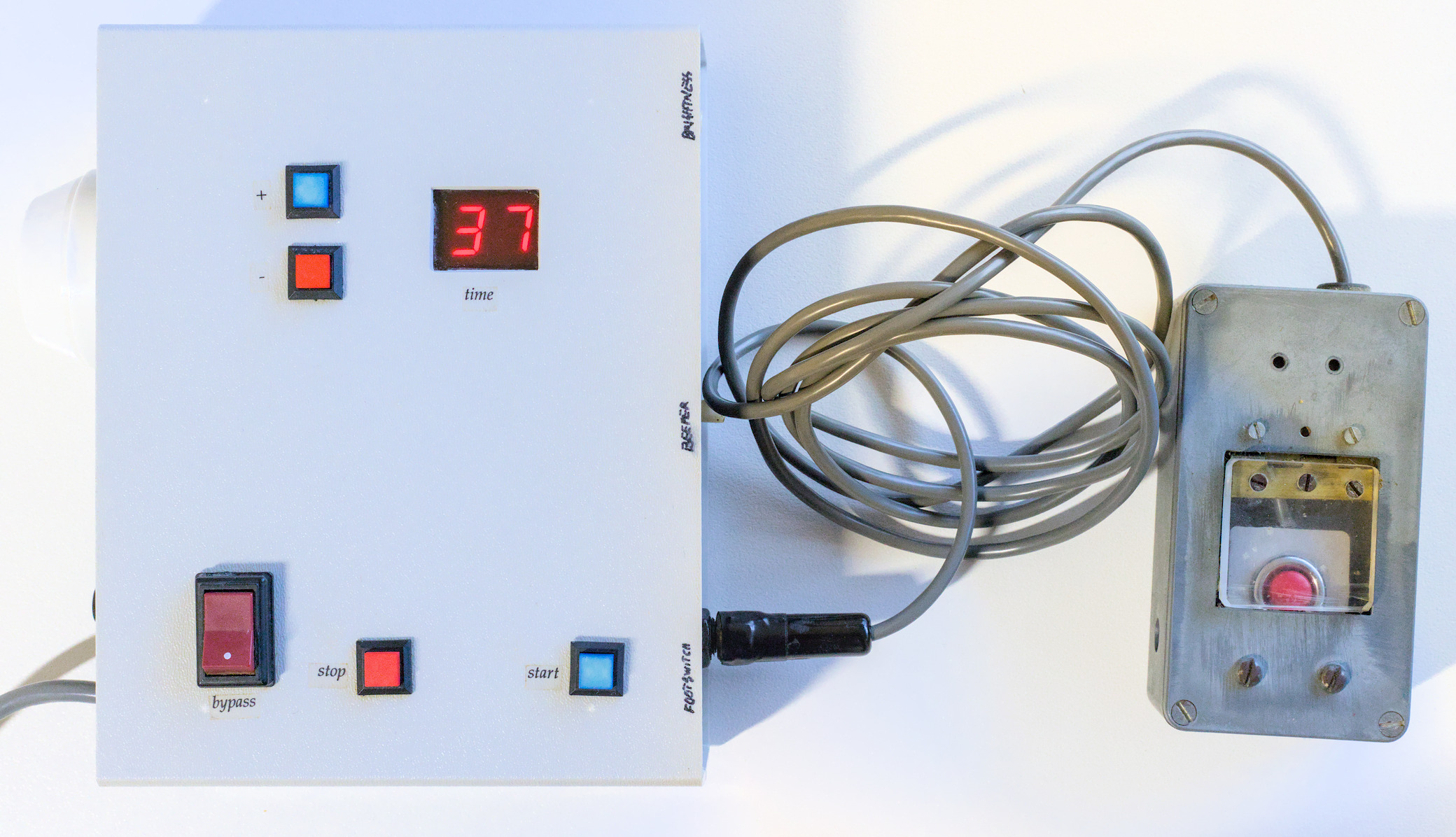
The timer with the optional foot-switch plugged in. The foot-switch was constructed in a die-cast metal box, and consists of a fairly robust push button with a hinged acrylic pedal on top of it.
Operation 🔗
- Plug the timer into a wall socket
- Make sure the bypass switch is off and plug the enlarger into the timer
- Turn the power on at the wall.
- Use the bypass switch to turn on the enlarger for focusing and composition.
- Use the up and down buttons to set the desired time. Holding down a button will cause it to repeat.
- Switch off the bypass switch when you're ready to print.
- Press the start button or tap the foot-switch to switch on the enlarger and begin the countdown. The beeper will beep every second during the countdown, which allows you to accurately time short burns and dodges.
- If you need to interrupt the countdown, press the stop button.
- At the end of the countdown (or when the stop button is pressed), the enlarger will switch off and the timer will reset to the desired time, ready for another exposure.
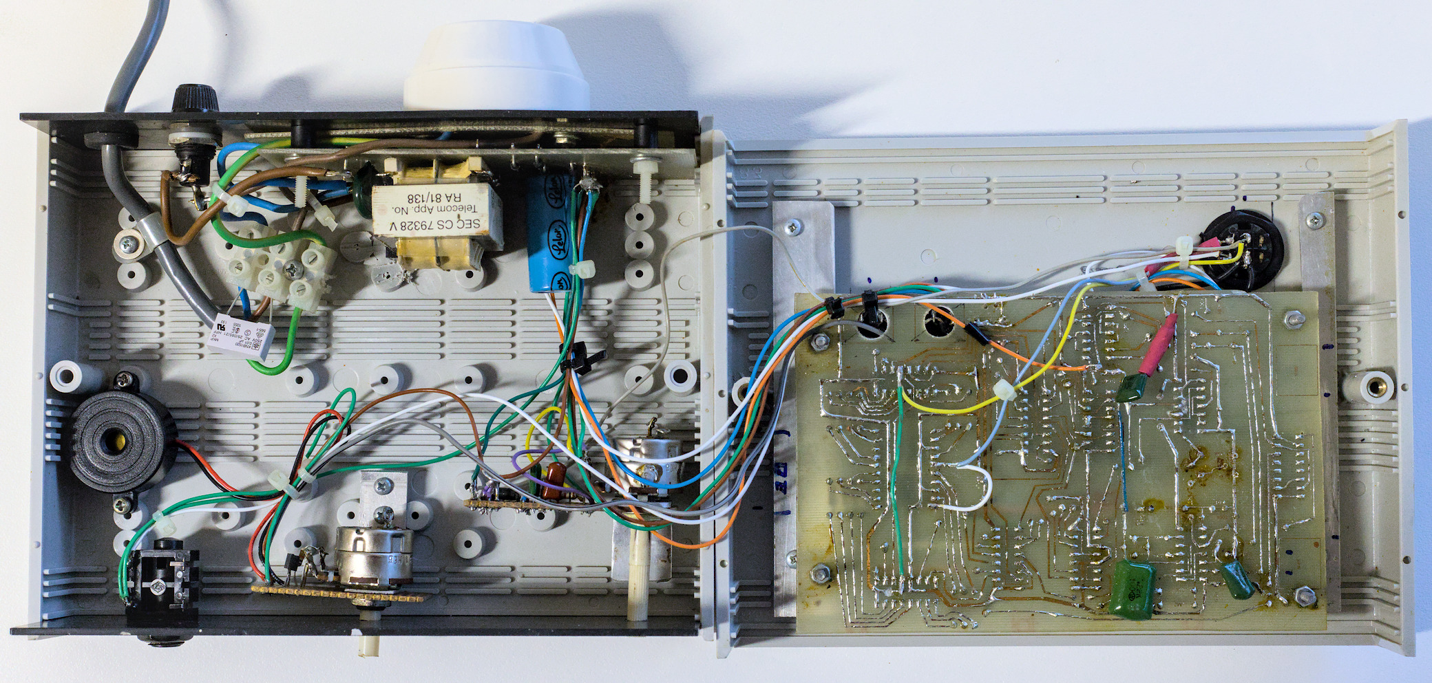
Inside the prototype. The beeper and brightness control circuits are on separate boards, and the main PCB has been patched with jumpers and a few other components to arrive at the current design.
Before you start 🔗
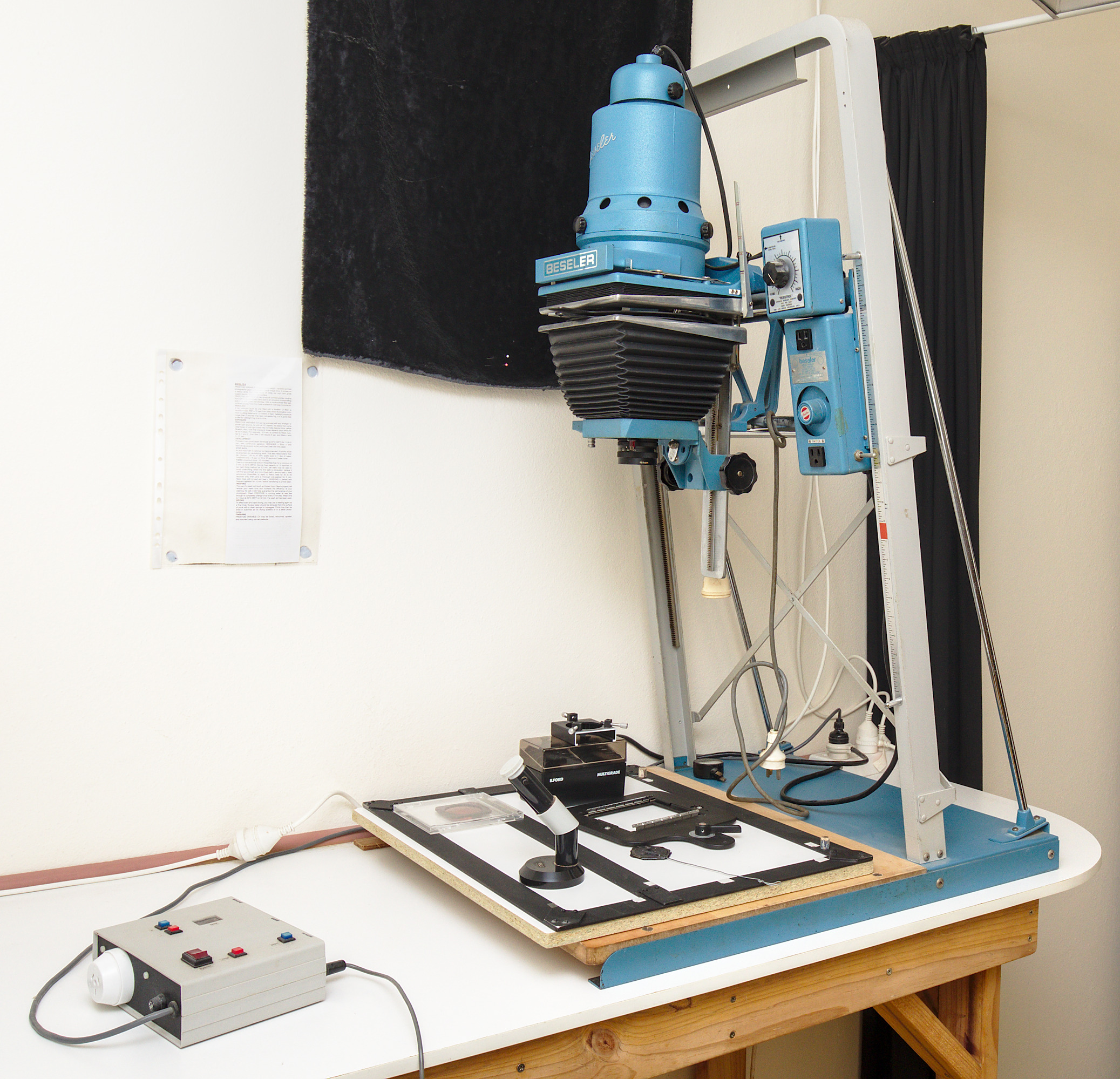
- I've only built one unit, but that prototype has worked well for many years, switching both a Durst colour head and a Besseler 4x5 B&W enlarger reliably. As you can see from the photographs, the prototype needed some patching, and I added the brightness control and beeper features afterwards. Those changes have been incorporated into the circuit presented here.
- There's always the possibility that I've made an error transcribing the circuit into KiCad. I have also not tested the universal timebase option. I recommend that you breadboard the circuit before getting PCBs made.
- You need to be competent and experienced working with circuits that handle mains voltages.
Construction steps 🔗
- Install KiCad, an open source electronics design application. See https://www.kicad.org/
- Download and open my KiCad enlarger timer project.
- Adjust or replace the footprints for your transformer, relay, 7-segment displays and any other components that might have different sizes to those in the project.
- If you don't have a 50Hz mains supply, incorporate the universal timebase option (included in the KiCad project) into the schematic and update the PCB.
- Generate the Gerber and drill files for your PCBs and get them manufactured.
- The PCB render below shows pin sockets for the external connections. You can just solder the wires on instead, and I've excluded the pin sockets from the bill of materials.
- If you use a metal case, make sure you earth it.
Design and layout 🔗
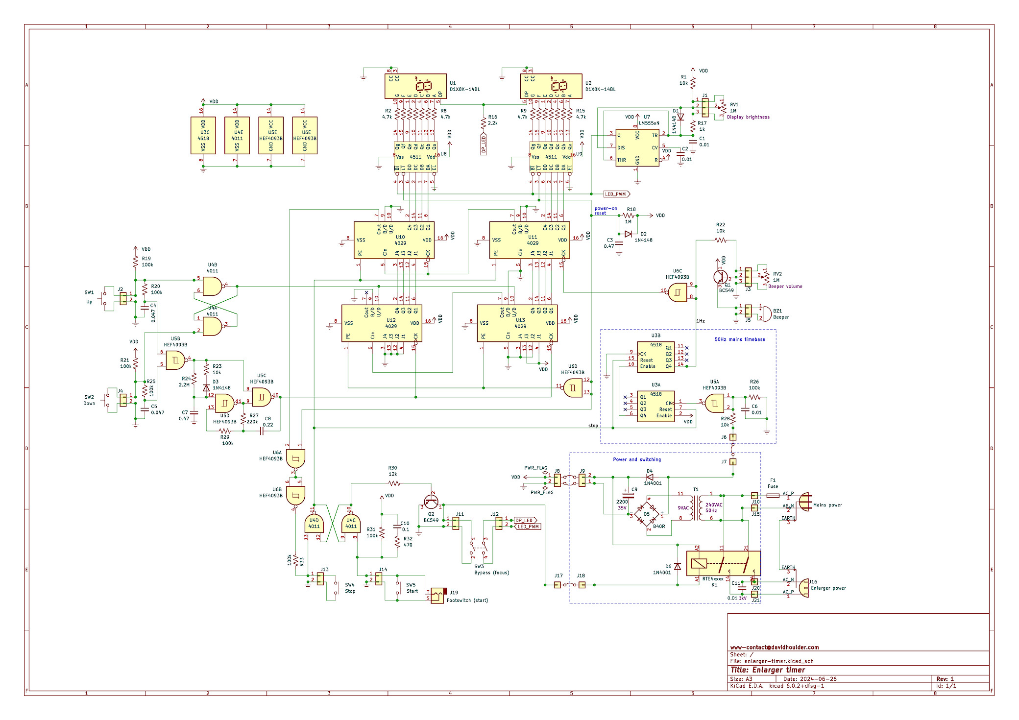
See the PDF version of the schematic for a more readable view. This is the 50 Hz mains version. See the KiCad project for all the details, including the universal timebase option.
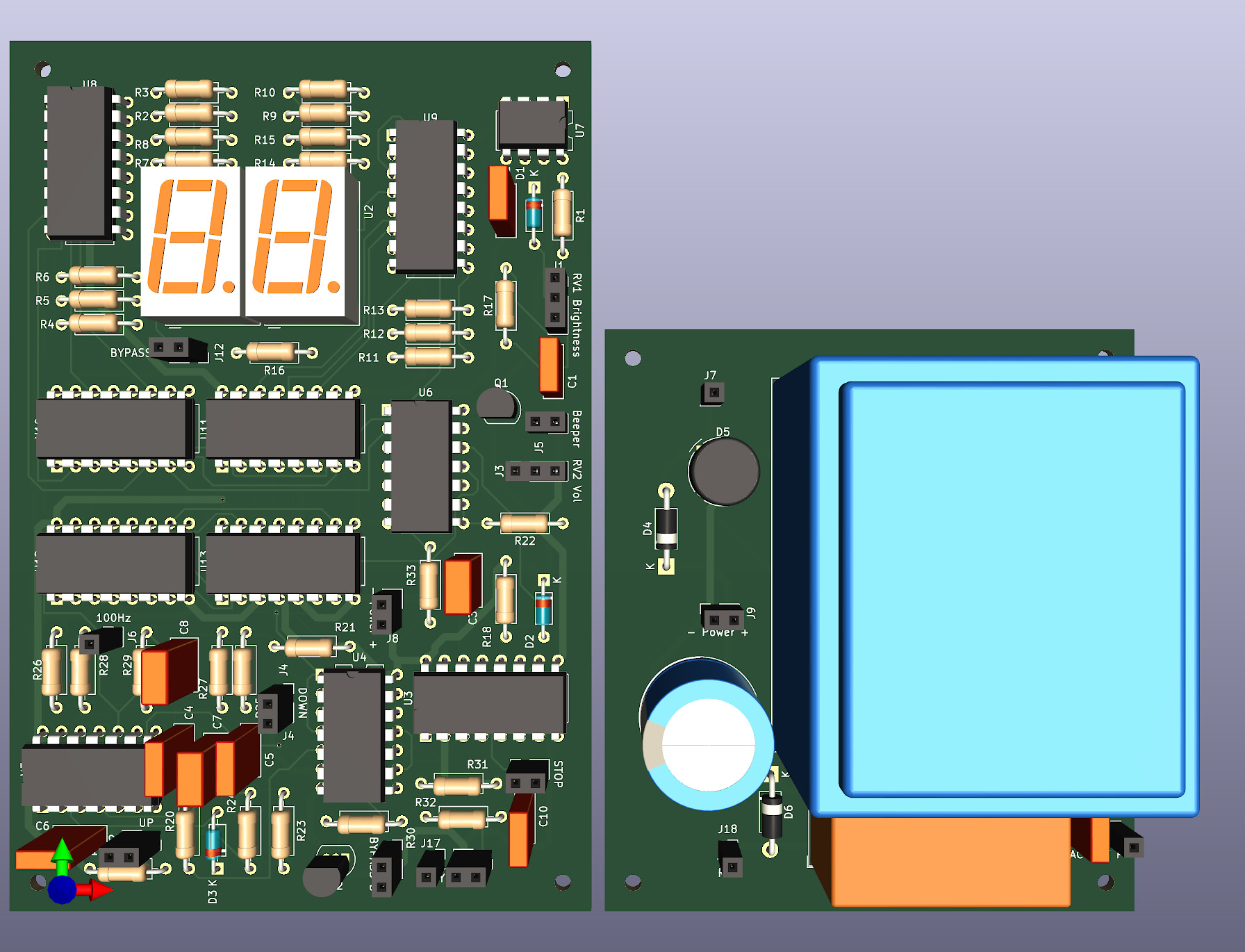
3D render of the circuit boards, generated from the schematic above. This incorporates all the circuitry seen in the prototype onto two double-sided PCBs.
How it works 🔗
The design in the main schematic uses the 50Hz mains frequency as a timebase. This is full-wave rectified to 100Hz, filtered by C6 and R26 to remove spikes, then divided by 100 by U3 to a 1Hz pulse train. There's a universal timebase option that uses a crystal for timing which should allow use with a 60Hz mains supply. U6C inverts the 1Hz signal to ensure the counter steps down at the end of each 1s pulse instead of stepping on the rising edge. This pulse train is inhibited when the timer is in its stopped state by keeping pin 7 of U3 (reset) high.
U12 and U13 form the time-setting counter. The up and down buttons toggle the up/down pins via the flip-flop formed by U4A and U4B. That up/down state is set from the buttons before the debounce filtering on the U5B inputs to ensure it is set before the count is changed. U5C and U5D perform the auto-repeat function. R24 and C7 determine the repeat delay, and R27 and C8 determine the repeat rate. When the timer is in its stopped state, this count is passed through to the countdown counter (U10 and U11), and then onto the 7 segment displays.
The start and stop buttons toggle the flip-flop formed by U4D and U4C. C10 and R32 prevent false triggering when the foot-switch is plugged in, as the cable can pick up noise.
When the timer is started, the 1Hz pulse train from U6C is enabled, and the preset-enable inputs of U10 and U11 are pulled low so that the countdown counter starts running. When the count reaches zero, the input on U4D is pulled low and the timer returns to its stopped state, which causes the time-setting count in U12 and U13 to be propagated through to the countdown counter and the 7-segment displays again.
Resources 🔗
- KiCad, the open-source CAD software used for this project
- Enlarger timer KiCad project (zip file)
- Schematic (PDF), including the 50Hz mains timebase
- Schematic for the universal timebase (PDF) option